Design, development, and evaluation of a proof of concept variable position mid wheel drive system for power wheelchairs
ABSTRACT
Front, mid, and rear wheel drive systems for power wheelchairs each have advantages and disadvantages as a function of the terrain and environment. The current project reports on the design, fabrication, and evaluation of a proof of concept model, PofCModel, for a variable position mid wheel drive system for power wheelchairs. The PofCModel provides a 38.1 cm range for the position of the drive wheels. A series of tests were conducted representing different terrains. Where appropriate performance was evaluated using time and course deviation measures or vibration with accelerometers positioned at the seat and shoulder positions. Results are presented as a function of the test condition and drive wheel position. As a feasibility study the focus was on determining the benefits of the variable position system.
KEYWORDS
Power wheelchairs, mobility
BACKGROUND AND SIGNIFICANCE
Cooper et al (1, p 45), in a discussion about costs, payers, and benefits, stated
From the viewpoint of an insurance provider, obtaining an electric-powered wheelchair from lowest bidder may make sense–but is also assumes the majority, if not all, of such chairs are in most respects the same.
Of course, this in not true. Simply try comparing the driving performance of a front-wheel to a center- or rear-wheel-drive base. Each has unique performance characteristics and meets the needs of different individuals.
In a similar vein, Gilinsky et al (2, p 14), in discussing the issues in selecting power equipment, stated
It must be determined whether a rear-wheel, mid-wheel, or front-wheel drive system would work best in their environment and lifestyle. The need for different types of maneuverability indoors and outdoors and the patient’s ability to safely drive these systems contribute to the decision.
Power wheelchairs have either front, mid, or rear drive wheel systems. Each has advantages and disadvantages (3, focus group results with a professional staff). The mid wheel system is especially maneuverable for indoor use; however, front and rear wheel systems are potentially more satisfactory for outdoor environments on uneven terrains. The present paper reports the design, development, and fabrication of a power wheelchair base with a variable position drive system that has a fore/aft adjustment range of 38.1 cm, which allowed evaluation of rear, center, and front-wheel drive configurations in a proof of concept model (PofCModel).
A focus group of professional staff, who work extensively with power wheelchair users, supported the potential value and benefits of such a system. A follow-up focus group of power wheelchair users also supported the concept if it would increase their ability to function more independently. For example, they would like to change their estimated ratio of indoor to outdoor use from approximately 80/20 to more outdoor use.
The purpose was to construct and evaluate a PofCModel that incorporated a single power wheelchair base with a consistent weight, one programmable controller, one joystick, one bearing setup, one suspension setup, and the same two motors and gear boxes but was equipped with a variable position drive system that can be adjusted fore/aft over a range of 38.1 cm.
METHODS AND RESULTS
Design, development, and fabrication of the PofCModel
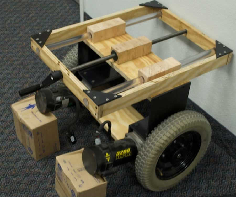 Figure 1. Model of variable position mid wheel drive system for power wheelchairs.
The purpose of the PofCModel was to establish the feasibility of the innovation, that is, to show benefits for different drive wheel locations for different operating environments. To this end the design goals were established:
- To be consistent with currently available popular mid-wheel drive power wheelchairs in the following characteristics:
- Dimensions–length, width, clearances, etc.
- The weight of the PofCModel, with and without batteries.
- The positioning of the batteries can be changed to match those used in different power wheelchairs.
- Seating adequate to test with a 100 kg dummy or equivalent mass to simulate a user.
- Programmable control system commonly used on power wheelchairs.
- Motor/braking system typically used on power wheelchairs
- To have the unique characteristics:
- Drive wheels that can be repositioned front to rear over a range of at least 36 cm.
- Front and rear casters with suspension that can be repositioned to function either as anti-tippers or as load bearing casters depending on the position of the drive wheels
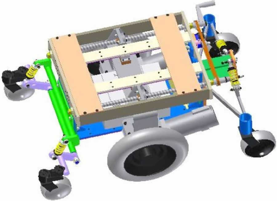
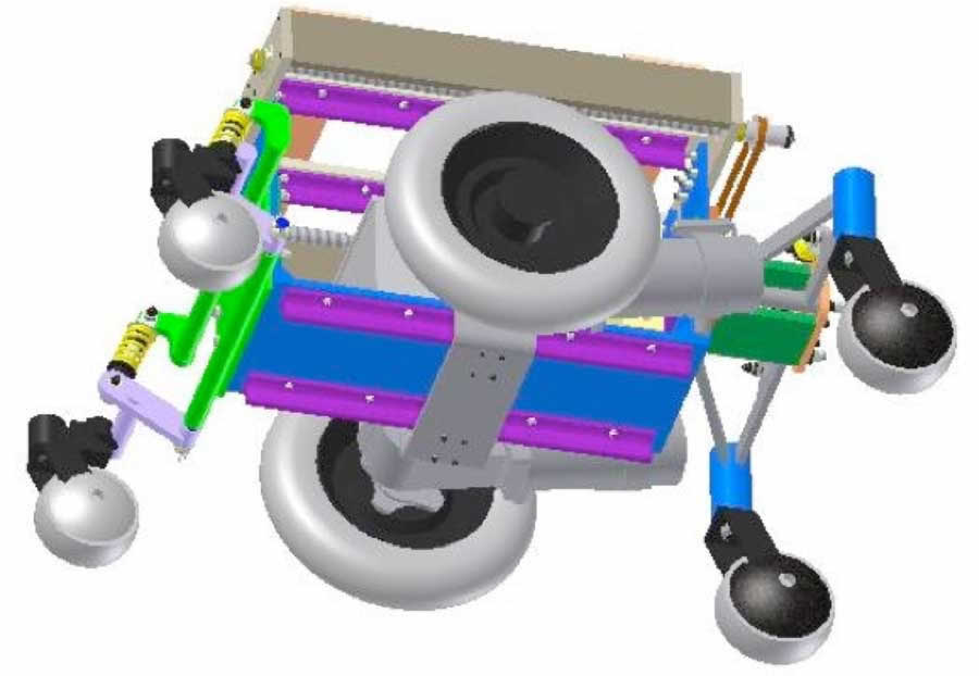 Figure 2. Top and bottom perspective views of the power wheelchair engineering drawings showing the double screw system for the variable position mid wheel drive and the track system to provide rigidity.
The PofCModel was designed so that the gearboxes, motors and controller from an Invacare Torque SP could be used. The mechanism to move the drive wheels was the critical design component for the PofCModel. A preliminary model was built, shown in Figure 1, to explore and determine the engineering requirements. The model shows a single screw mechanism with bearing guides on either side to change the position of the drive wheels. Engineering considerations then led to the engineering drawings in Figure 2 that show the mechanism, a double screw combined with a double bearing guide system.
The use of the double screw provides an inherent braking system. The upper figure, from a top perspective, shows the screw mechanism and the lower, from a bottom perspective, shows the undercarriage with the bearing guides. A simple belted crank mechanism is used to change the position of the drive wheels for the PofCModel (an electric motor will be integrated into a full prototype).
A photograph of the fabricated PofCModel is shown in Figure 3.
When the drive wheels are in the full front position, the front casters lift out of the way.
Evaluation of the PofCModel
TEST # |
Individual Task |
Dependent Measures |
1 |
Turns 90 degrees left and right while moving forward at 100% or 50% power |
A |
2 |
Turns 180 degrees left and right in place (fixed area) |
T, M |
3 |
Maneuvers left and right sideways |
T, M |
4 |
Gets through doorway with 90 degree turn |
T, M |
5 |
Rolls 20 m on 0, 2.5, 5 degree side slope, at full power |
Deviation from center line over 20 m, or distance to go off course |
6 |
Ascends 10 degree incline, at 100% and 50% power |
A, T |
7 |
Descends 10 degree incline, incline, at 100% and 50% power |
A, T |
8 |
Rolls circular course around tree on playground sand surface, approximately 25m, left and right at 100% power |
A, T |
9 |
Gets over 15cm wide by 5 cm deep pothole |
A, |
10 |
Gets over 2cm threshold at 100% and 50% power |
A, |
11 |
Ascends 5cm level change at 100% and 50% power |
A, |
12 |
Descends 5 cm level change at 100% and 50% power |
A, |
13 |
Ascends 10 cm curb at whatever power level it takes to pass |
A, Pass or Fail |
14 |
Descends 15cm curb at a safe power level |
A, |
15 |
Traction (see ISO 7176-13) Wet: Concrete, asphalt, gravel, grass |
Strain gauge |
| Key: A = Acceleration, measured in three dimensions; T = Time to complete task; M = Number of maneuvers to complete task | ||
The goal for the evaluation of the PofCModel is to show that optimal performance is a function of both the drive wheel placement and the terrain/environment. Therefore a series of test conditions were developed to determine whether or not the drive wheel position interacted with these different environments.
The conditions ranged from traditional indoor maneuvers such as turning 90 degrees to go through a doorway to open field performance. The choice and design of tests drew on the Wheelchair Skills Test (4), the input of power wheelchair participants in a focus group, and clinical experience. The Focus Group participants expressed strongly the need to evaluate the drive system on different surfaces such as wet surfaces including grass, soft surfaces, and uneven gravel. The list of conditions is shown in Table 1, with a brief description of the condition (test) and the dependent measures. Accelerometers (MSR-145) placed at the seat and shoulder position allow measurement of the vibrations on three axes, which is an important consideration in usability (5).
Each test condition is evaluated at least twice with the drive wheels in the front, mid, and rear position. The driver is one of the authors, whose mass with added weights totaled approximately 100 kg. A second staff person is to complete several of the tests to insure that there is consistency.
When a wheel position effect is found, additional trials will be conducted to determine more precisely the function underlying the relationship. For example, assume a test for which there is reduced vibration when the drive wheels are in the rear position compared to the mid or front position. How far back do the drive wheels have to be to obtain the benefit?
DISCUSSION
The data, which will be collected and analyzed between late January and mid March 2010, will be a central part of the RESNA presentation. The anticipated result are that they will show “benefits”–optimized performance obtained as a function of the terrain/environment–for the variable position drive system, which would support further development through a Phase II SBIR project. However, the failure to find “benefits” is a research contribution in and of itself.
REFERENCES
- Cooper, R. A., Cooper, R., & Boninger, M. L. (2008). Trends and issues in wheelchair technologies. Assistive Technology, 20, 61-72.
- Gilinsky, G., Cody, P., & Hosack, K. R. (2008) Considering power: Choosing power equipment depends on a variety of complex interrelated factors, Rehabilitation Management, 21, 14-17.
- Woods, B. & and Watson, N. (2003). A short history of powered wheelchairs. Assistive Technology, 15, 164-180.
- Wheelchair Skills Test 4.1 downloaded from www.wheelchairskillsprogram.ca/eng/4.1/WST_Manual_Version.1.51.pdf as well as related materials.
- Wolf, E., Cooper, R. A., Pearlman, J., Fitzgerald, S. G., & Kelleher, A. (2007). Longitudinal assessment of vibrations during manual and power wheelchair driving over select sidewalk surfaces. Journal of Rehabilitation Research & Development, 44, 573-580.
ACKNOWLEDGEMENTS AND IP
This project was supported by NIDRR SBIR Phase I grant H133S090013 and an Indiana 21st Century Matching grant to Criterion Health, Inc. Stephen Sprigle, through the RERC at the Center for Assistive Technology and Environmental Access, Georgia Tech, provided invaluable assistance. John Layer, Ph.D. provided mechanical engineering consultation and Dan Goebel, Professional Consultants, Inc., completed the engineering design work. Criterion Health, Inc. has, based on the results of patentability searches, patent pending status on the drive system and associated new art.
AUTHOR CONTACT INFORMATION
Robert M. Levy, Criterion Health, Inc., 6321 Tanglewood Rd. Terre Haute, IN 47802, (812) 894-2120, bobl@criterionhealth.net